tisdag 6 september 2011

Acer AL1711 power supply failure


Acer AL1711, manufactured in December 2004, model no. ET.L1307.214

The screen would rapidly flash its power LED, without any other sign of life.

All electrolytic capacitors, except for the main rectifier capacitor and C121 and C120 (to the right of the transformer in the picture), had failed. C117 and its mate were collectively and successfully replaced by one 16V/1500µF Chemi-Con KZG. It was, however, later replaced by a pair of 25V/470µF Nichicon HE, due to the KZG being too tall to fit in the casing. The capacitor between the heatsink and the CFL transformer was also replaced by one 25V/470µF Nichicon HE. They are all situated on a roughly 12V rail, so using 16V caps is no problem.

Acer AL1716 power supply failure

Acer AL1716, manufactured in July 2006, Model no. ET.1716P.175

The screen would flash its power LED and squeal. The backlight would not come on.

All electrolytic capacitors in the power supply, except for the main rectifier capacitor and the small one by the transformer, had failed. Replacement by Nichicon HE and Chemi-Con KY of the same values fixed the issue.

lördag 27 augusti 2011

Heated, seated hell from France


I live in Finland.

We get kind of cold winters in this part of the world, and as a function of that, heated seats have come standard in pretty much every car sold around here the last forty years, my Pug being no exception to that, but twenty years of butt had taken its toll on the front seat heaters, of which neither worked.

The coldest couple of days last winter, the heater core in aforementioned Peugeot froze, and as the only then-running vehicle of the household, the hour-long, -40°C drive to various workplaces was rather dreadful to say the least. I promised myself to fix the heated seats before that had a chance to happen again.

Getting the seats out was a dreadful business upon itself, which consumed about an hour and a half per seat. That was only the beginning. The real time muncher lied in these:

The seat covers are attached using what appears to be bits of copper wire, jammed through the covers, cushion and metal grille. Removing them without ruining at least one of the components is a time-consuming process.

Upon breaking into the darned thing (and slicing the heater up), the problem becomes quite obvious.


Fixing it could be as quick as just jamming the cable back in, but I did it properly, with solder, some more wire, heat-shrink tubing and patience.


Tuck it back and seal it up!

I took the liberty of improving the cover attachments a bit:

And then I just mounted the seat back and buckled up for the driver's seat. I knew that it would have graver issues than the passenger seat.

fredag 8 juli 2011

Samsung 225BW power supply failure


Samsung 225BW, manufactured in March, 2007, Model no. LS22DPWCSQ7EDC

All electrolytic capacitors, except for the main rectifier capacitor, in the power supply had failed. Replaced with Nichicon KY of similar values. C304 and C305 replaced with 470µF and 220µF respectively due to lack of more fitting replacements. They are connected in parallel. C112 successfully replaced with a 220µF part.

Several capacitors were failed on the logic board as well, causing issues with screen wake-up from sleep, as well as occasional flickering.

lördag 2 juli 2011

Ash tray? Power button.


My car radio stereo, unlike most, doesn't have a power switch integrated into it (for the reason of it not actually being a complete system, but only a DSP and power amplifier). Due to recent generator troubles in my car, I've been using the very rudimentary power switch, consisting of two wires in the ash tray in series with a relay, more and more.

Since I don't smoke, and I wouldn't even consider letting anybody smoke in my car, I thought I'd proceed with using the ash tray area, since it didn't really have any purpose other than storage space for the cigarette lighter when I use the power socket.

The parts used were one APC Smartslot cover, one hefty 10A switch from an old analogue TV transmitter control panel, the ash tray of my car, as well as an LED, a resistor and some wiring.


Some crude bending and drilling later, the switch was mounted. I didn't have a large enough drill bit available, so I had to pry the last millimetre or so of the hole open by forcing my side cutters through it. Inefficient but ultimately effective.

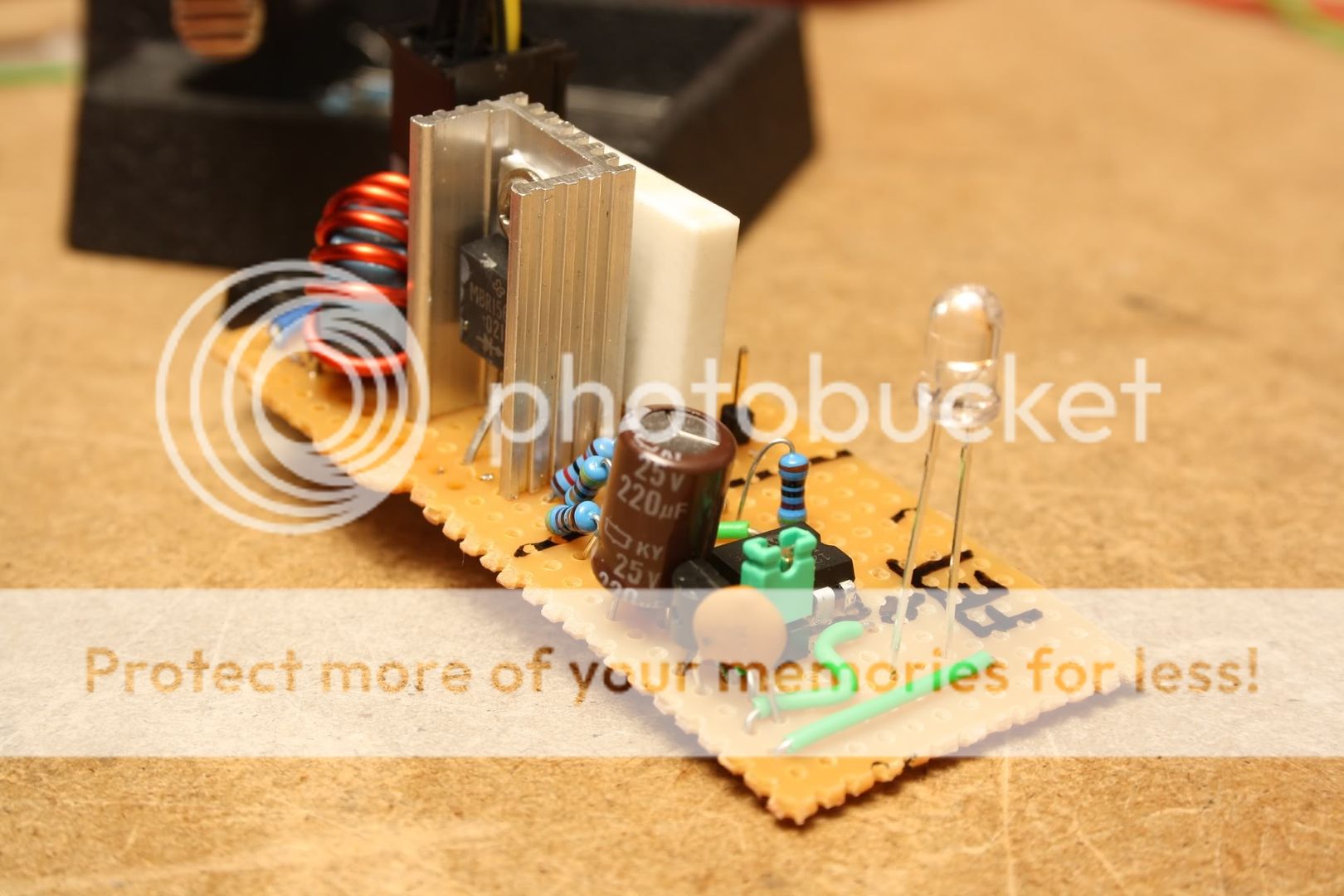
Another smaller (thankfully!) hole and some soldering later, it's starting to come together.


The tape used to hold the LED in place is heat-resistant tape from Dealextreme. One of the most versatile assets there are, I think. In hindsight, I should have used different colours for the wires going to the switch, as there actually is a difference between them, caused by the LED; if I hook them up the wrong way, the LED will shine constantly when there's power, regardless of the switch position. Oh well, it's a minor thing. The black wire is ground for the LED.

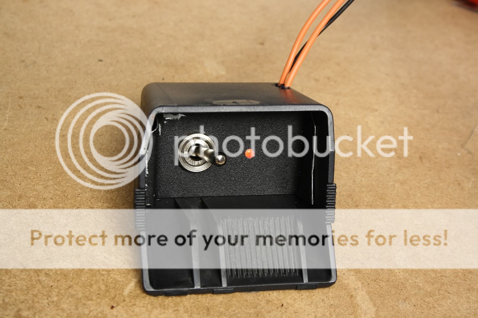
Finally, this little box came into existence:


I'm rather satisfied with the mounting mechanism for the metal plate holding the switch. Since the ash tray gets ever-so-slightly thinner at the back, there's nothing more to it than to slide it in. It sticks extremely well without the aid of either screws, tape or glue.


It is a lot more user friendly now; I can actually turn the radio off while driving!

fredag 1 juli 2011

PIC based 10kHz Roth desulfator

A while ago, I did some research about battery desulfators, and I have since then built this breadboard prototype out of junk box components. It's essentially the same design on the power side of things, although the coil is unknown, but seemingly capable of delivering a similar current pulse as the one Carpenter used in his design.


There's a key difference on the logic side, though, and that is the use of a PIC12F629 for delivering the MOSFET gate drive, rather than a 555 timer and a dedicated MOSFET driver. The use of a rather easily driven, logic-level FET and a µc capable of delivering a reasonable amount of current allows for this configuration without excessive time spent in the linear region of the FET.

I forgot to take any pictures of the gate of the FET, though, but I assure you that they're more than acceptable; There's hardly any heat generated in the FET at all.

I've measured a peak current pulse of about 5.5A across the 0.11Ohm sense resistor, and an RMS current consumption of about 40mA during operation.

Scope shots taken with a 3Ah flooded moped battery:

Across Rsense:


Across the battery terminals: